Some basic manufacturing parts commonly used in Body in White (BIW) fixture design are Mylar, Pin, Blade, L Block, Pin Block, Riser, Weldment, etc.
Shimming:
Using thin plates of varying thickness to adjust gaps or ensure a better fit. The thickness of shims can range from 0.25mm to 2mm, and shimming itself can be of different thicknesses, such as 5mm, 8mm, or 10mm. The purpose of shimming is to address manufacturing errors and achieve the desired fit between Mylar and Panel by adjusting gaps in the X, Y, or Z directions.
There are three types of shimming: one-way, two-way, and three-way. The choice of shimming depends on the NC cut angle and PIN angle with the car line. If the NC cut is less than 15 degrees, one-way shimming is used. For NC cuts greater than 15 degrees in one direction, two-way shimming is applied. If the NC cut has angles exceeding 15 degrees in two directions, three-way directional shimming is utilized.
The case for pins involves different criteria. If the pin’s angle with respect to the car line is not more than 15 degrees, two-way directional shimming is employed. However, if the pin’s angle exceeds 15 degrees in any direction, three-way shimming is used for adjustment.
This information provides a comprehensive overview of the basic manufacturing parts and shimming considerations in BIW fixture design, offering insights into the methods used to address manufacturing errors and achieve the desired fit.
MYLAR :
Definition of Mylar: Mylars are blocks that come in contact with the panel and serve to hold or clamp it in place. They are designed in CAR LINE. Generally, Mylars are made of Steel.
Alternative Name: Mylars are also referred to as NC (Numerically Controlled) Blocks, suggesting a connection to computerized or automated manufacturing processes.
Adjustability: Mylars are mounted on blocks or plates using shimming, allowing for the adjustment of the Mylar height during assembly. This adjustability is likely crucial for achieving precision in the manufacturing process.
Material Variation:
For ‘A’ class surfaces, Nylon Mylars are specified. This choice is likely made to prevent scratches and maintain the quality of the surface finish.Shimming Types: Shimming, the process of inserting thin pieces of material to adjust the height, can be 1 directional, 2 directional, or 3 directional, depending on the requirements of the NC cut. This suggests a need for flexibility in adjusting the Mylar height in different directions.
Overall, Mylars play a significant role in ensuring the accuracy and quality of panel assembly, especially when dealing with surfaces that require a high level of finish, such as ‘A’ class surfaces. The integration of Numerically Controlled processes and the use of Nylon Mylars highlight the precision and technology involved in this manufacturing context.
PIN:
Pins are used to lock the rotational movement of a panel, with different types of pins such as Round Pin and Diamond Pin. The use of two and three-directional shimming depends on the angle of the pin with respect to the carline. Additionally, collared pins are used when the pin is meant to support the panel, and in such cases, 3-way shimming is provided regardless of the pin’s angle to the carline.

BLADE :
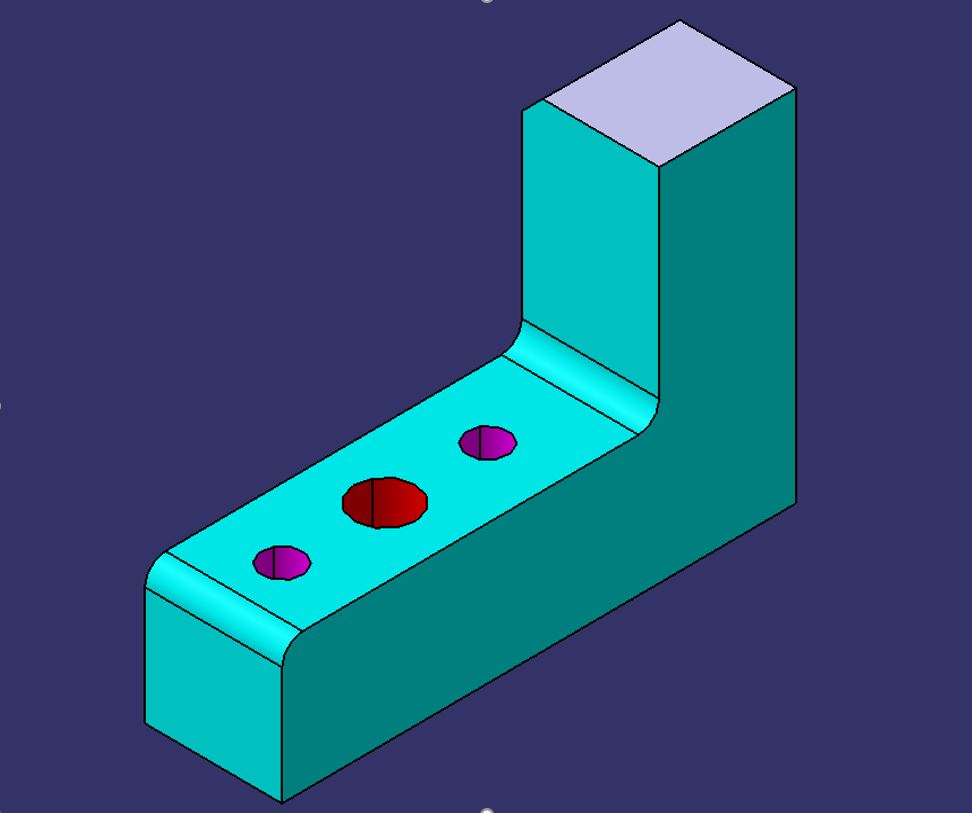
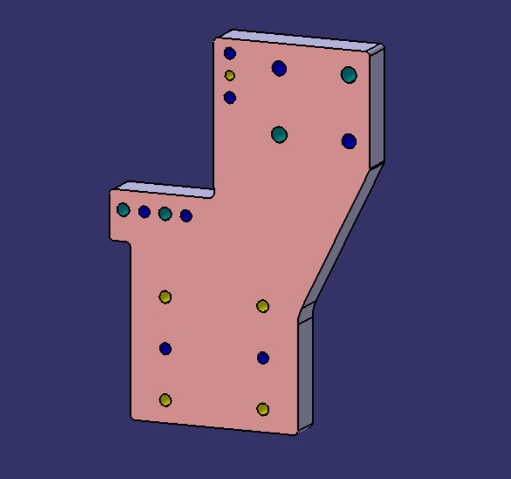
The plate connecting the Riser to the Clamp cylinder is referred to as the “Blade,” and its design is crucial for the unit’s construction, keeping it compact is a key consideration. Compact design is often important for efficiency, space utilization, and overall functionality.
When designing the Blade, you may want to consider factors such as material strength, weight, and the specific functions it needs to perform within the unit. Additionally, the choice of material, manufacturing process, and any required structural features should align with the overall goals and specifications of the unit.
If the plate can be of any shape, it allows for flexibility in design. Depending on the requirements, you might explore geometric shapes that optimize strength and reduce material usage, contributing to the desired compactness.
It’s essential to collaborate with engineers and designers, conduct simulations or prototypes, and iterate through the design process to ensure that the Blade plate meets all necessary criteria. The goal is to create a plate that not only connects the Riser to the Clamp cylinder effectively, but also enhances the overall performance and reliability of the unit.
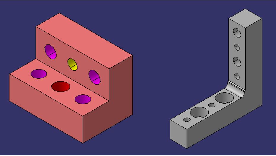
L BLOCK :
L blocks and T blocks seem to serve as versatile elements in various applications. The L-shaped block, or L block, appears to be employed for shimming and connecting different components, providing flexibility in its usage. Additionally,L block can be utilized for purposes beyond shimming, adapting to specific requirements in connecting various parts.
Similarly,T block, which has a T-shaped configuration. Like the L block, the T block likely serves as a versatile connector, possibly used for joining parts together or providing structural support.
Overall, these blocks seem to play crucial roles in assembly and connection processes, offering adaptability to different needs within the context of Mylar and Blade connections.
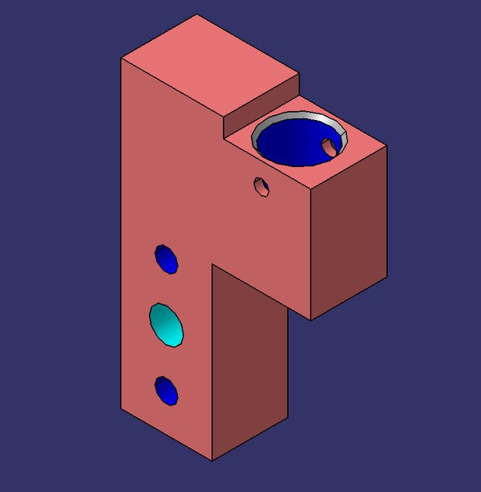
PIN BLOCK :
Alignment and Positioning: Pin holders are employed to ensure precise alignment and positioning of workpieces within the fixture. This is essential for accurate and consistent manufacturing processes.
Fixture Design: Manufacturing fixtures are designed with slots, holes, or designated areas to incorporate pin holders. These holders are strategically placed to support the use of pins for holding and locating the workpiece.
Variety of Pins: Different types of pins may be used in manufacturing, including round pins, diamond pins, and tapered pins. Pin holders are designed to accommodate these various types of pins based on the specific requirements of the manufacturing process.
Material Compatibility: Pin holders are typically made from materials that provide durability, stability, and resistance to wear. Common materials include steel, aluminum, or other alloys, depending on the application and the forces involved during manufacturing.
Interchangeability: Pin holders are often designed to be interchangeable, allowing manufacturers to adapt fixtures to different workpieces or production requirements easily.
Fixturing Systems: In some cases, pin holders are part of larger fixturing systems that include other components such as clamps, supports, and locators. These systems work together to ensure the stability and precision of the workpiece during manufacturing.
Automation: In automated manufacturing processes, pin holders may be integrated into robotic systems or CNC (Computer Numerical Control) machines to enhance the efficiency and repeatability of the production process.
Customization: Depending on the specific manufacturing needs, pin holders can be customized in terms of size, shape, and features to meet the requirements of a particular application.
Overall, pin holders contribute to the overall effectiveness and precision of manufacturing fixtures, helping to maintain consistency, reduce errors, and improve the efficiency of production processes.
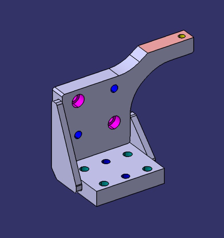
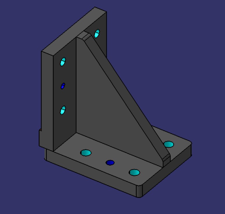
RISER :
A riser, is a component mounted on a baseplate that holds a clamp or pin cylinder. It can be either a standard part or a manufactured part, and it may come in different shapes and sizes depending on the project requirements. Additionally,a riser can be a single part or a welded part.
In engineering and manufacturing, risers are often used to elevate certain components or structures to a desired height. The choice between a standard or manufactured riser, as well as the decision to use a single part or a welded assembly, would depend on the specific needs and specifications of the project.
WELDMENT :
The specific dimensions for overlay and welding considerations can vary depending on factors such as the type of welding process, material thickness, and the welding specifications for a given project. It’s essential to follow industry standards, welding codes, and design requirements to ensure the integrity and quality of the weldment.
Additionally, weldments can indeed vary in size and complexity, involving any number of plates depending on the design and structural requirements of the final assembly. The choice of welding method, such as arc welding, MIG (Metal Inert Gas) welding, or TIG (Tungsten Inert Gas) welding, may also depend on the specific characteristics of the materials being joined and the overall application of the weldment.